Cogs, often referred to as gears, have teeth carved onto the gear wheel or cogwheel. The torque and speed are transferred via the meshing of these teeth. Gears are mechanical devices that use the lever principle to shift the power device’s direction, speed, and torque.
A gear is a rotary circular mechanism with teeth designed to transfer torque and speed from one shaft to another.
The teeth of gears are the components that enable contact with other gears, facilitating a change in motion. Well, in this reading, we’ll explore what gear teeth are, their parts, diagrams, types, designs, and configurations.
Let’s begin
What are Gear Teeth?
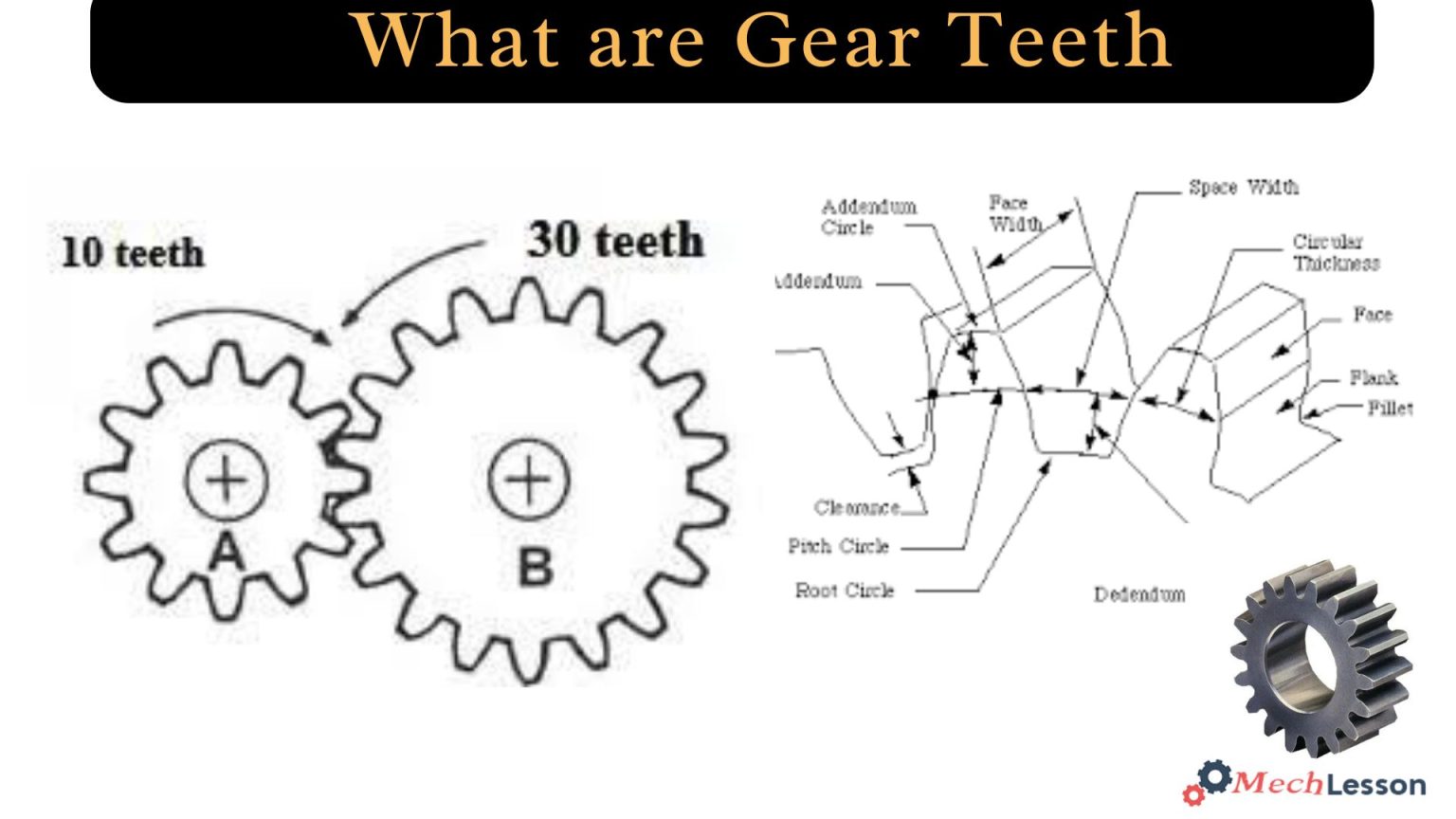
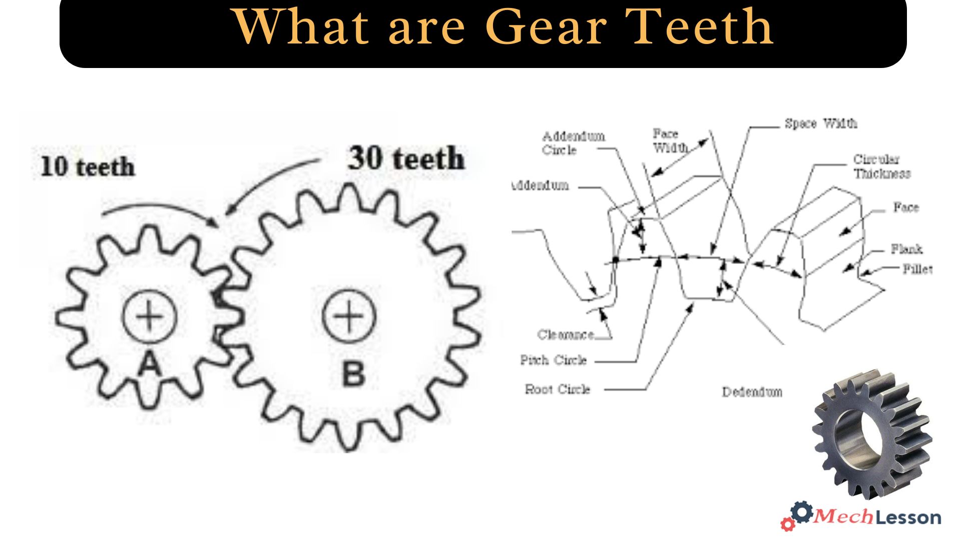
The parts of gears that allow contact with other gears and facilitate a change in motion are called teeth. One important metric in gear design is the pitch, which is the separation between identical spots on adjacent gear teeth.
Teeth, which are essential for avoiding slippage during power transfer, are what effectively characterise gears. Gear teeth have historically been referred to as cogs, and the construction, positioning, and shape of these teeth are crucial to the gear’s functioning and performance.
Although they can be placed one at a time, gear teeth are usually cut into a blank. If the teeth in blank-made gears deteriorate and break, the complete gear needs to be replaced.
The position and angle of the teeth, which might be helical or straight, depend on the kind of gear. The gear’s teeth can be flattened around the outside, placed internally on the inside, or arranged around the outside.
Although the fundamental construction of gear teeth might seem straightforward, their specific design is determined by a number of intricate factors and mathematical computations.
For both driven and drive gears, involute gear teeth are most often utilised. The diameter of the base circle dictates their form. Any gear with the same pitch, pressure angle, and helix angle can mesh with standard involute teeth.
Two involutes of the same spiral intersect at a single point, making contact.
Related: What are Gears? Their Types, Diagram and How it Works
Parts of Gear Teeth
Below are the necessary parts of gear teeth
- Gear teeth are defined by their profile, which typically features an involute curve.
- The top land of a gear tooth is the flat surface at the tooth’s tip, known as the face width.
- Tooth thickness (ts) is the arc length between the opposing faces of a tooth, measured along the pitch circle.
- The tooth face is the mating surface between the addendum circle and the pitch circle.
- The tooth flank is the surface between the tip and root surfaces of a gear tooth.
- The fillet radius, located at its base, is the area where bending stress concentration is highest.
- Tooth pitch is the distance between two points on adjacent teeth, measured at the pitch line.
- The pitch point of a gear tooth is the point where the pitch circles of two meshing gears are tangent to each other.
- The face width is the length of a gear tooth along its axial plane, enhancing both the tooth’s bending strength and surface strength.
Diagram
Gear Teeth Design and Configurations
Factors used in the design of gear teeth include:
- Face of a Tooth: Tooth surface outside the pitch surface
- Flank of a Tooth: Tooth surface inside the pitch surface
- Tooth thickness or Circular Thickness: Tooth thickness measured on the pitch circle, which is the length of an arc
- Root Circle: Circle bounding the spaces between the teeth
- Tooth Space: The distance between teeth
- Circular Pitch: The width of a tooth and a space
- Diametral Pitch: The number of teeth per inch of the pitch diameter
Configurations
Gear teeth are crucial characteristics of a gear, with their structure, placement, and profile influencing their performance. Teeth can be cut directly into the gear or inserted separately, depending on the type and application.
The tooth design affects rotational direction, with external teeth facing outward from the gear’s center and internal teeth facing toward the center. The tooth profile, which affects speed and friction, is influenced by factors such as involute, trochoid, and cycloid.
Gears are classified based on their positional relationship with their axes and gear pairs. There are three main classifications: parallel axis, intersecting axis, and non-parallel/non-intersecting axis.
In parallel axis configurations, shafts are aligned parallel to each other, while in intersecting axes, shafts are positioned at an angle or perpendicular to each other. Non-parallel and non-intersecting gears transmit rotational force through slippage between gear tooth surfaces.
Parallel axis gear configurations involve power transmission between parallel shafts, creating rolling contact for efficiency levels of 98% to 99.5%. Common gear types include double helical, helical, herringbone element, and spur gears.
Spur gears are low-cost but produce noise, while helical gears are better for high-torque applications due to their angled teeth and quieter operation.
Gears with a parallel axis configuration offer excellent reliability, ease of maintenance, and minimal components, making it the most common gear arrangement.
Gear Teeth Profile
Gears are classified based on their tooth profile, which is the shape of the cross-section of a tooth face by an imaginary cut perpendicular to the pitch surface.
The tooth profile is crucial for the smoothness and uniformity of the movement of matching gears, as well as for friction and wear.
Artisanal gears, such as those in the Antikythera mechanism, generally had simple profiles, such as triangles. Larger gears, like those used in windmills, were usually pegs with simple shapes inserted into a smooth wooden or metal wheel or holes.
This is achieved with equally simple shapes cut into such a wheel. This suboptimal profile resulted in vibrations, noise, and accelerated wear.
Cage gears, also known as lantern gears or lantern pinions, have cylindrical rods for teeth parallel to the axle and arranged in a circle around it.
They are more efficient than solid pinions and can be constructed with simple tools. Cage gears are sometimes used in clocks but should always be driven by a gearwheel, not used as the driver.
Mathematically, modern gears typically have a tooth profile designed to achieve a constant angular velocity ratio.
There is an infinite variety of tooth profiles that can achieve this goal, and given a fairly arbitrary tooth shape, it is possible to develop a tooth profile for the mating gear that will do it.
Parallel and crossed axes are commonly used for gears with constant velocity tooth profiles, based on the cycloid and involute curves. Cycloidal gears were more common until the late 1800s, but the involute has largely superseded it, particularly in drivetrain applications.
Related: What is Hypoid GearBox? Its Diagram and How it Works
FAQs
What are gear teeth?
Gears are one of the most important power transmission elements required to transmit both torque and motion between parallel and non-parallel shafts by means of progressive engagement of projections called teeth. Those parallel-axis ones, including spur and helical gears, are the most widely used types of gears.
What are the teeth on a gear wheel called?
A cog is a tooth on a wheel.
What is a synonym for gear tooth?
tooth on the rim of the gear wheel. synonyms: cog.
How many teeth do gears have?
The number of teeth depends on the ratio between the driver and driven shafts. The teeth must have the same module (or diametral pitch) and a minimum number of 17 teeth is recommended to avoid undercutting the teeth.
The module chosen depends on the size of the assembly, the gear ratio and the minimum number of teeth.