
An electrically controlled switch is a relay. A set of working interface terminals and a set of input terminals for one or more control signals make up the switch.
Any number of connections in different interface arrangements, such as making connections, breaking contacts, or any combination of both, may be included on the switch.
There are many types of relays out there to meet the demands of various applications. In this reading, we’ll explore what an electrical relay is: its functions, applications, components, diagram, types, and working principle. We’ll also explore its advantages and disadvantages.
Let’s begin!
Related: What is An Ignition Relay? Its Functions And Replacement Cost
What are Relays?
A relay is an electric switch that works with electromagnetism to convert small electrical stimuli to larger currents. When an electrical input triggers electromagnets to create or disrupt preexisting circuits, this conversion occurs.
Leveraging weak inputs to power stronger current, relays can effectively act as a switch or an amplifier for the electric current. These depend on the desired applications.
We also refer to relays as magnetically operated switches, which activate and deactivate upon the energisation of an electromagnet. The voltage applied to the relay input terminals energises the electromagnet. The relay was invented by the US scientist Joseph Henry in 1835.
Most electronic and mechanical appliances require relays to convert small electrical inputs into high-current output they receive. Traditionally, relays were used in long-distance telegraph circuits as signal repeaters.
In other words, transmitting the signal from one circuit to another refreshes it. Telephone exchanges and early computers extensively used relays to perform logical operations.
Functions of Relays
Below are the functions of electrical relays in their various applications:
- A relay’s primary purpose is to act as a switch when controlling circuits.
- Some relay types use an electromagnet to close and open contacts.
- It protects electrical circuits from overload or faults, serving as protective relays.
- Relay functions also allow a system to run only for a set period or to start only after a set period, thus known as time-delay relays.
- Another purpose of relays is for switching electric motors and lighting loads.
- A single relay can serve as a connector for multiple contacts, so they can all move together when the relay coil is energised or deenergized. If one of the contacts in the relay stops moving, the rest of the contacts won’t be able to move. Relays with this effect are also known as safety relays.
- Some types of relays have excellent functions where radio transmitters and receivers share one antenna. The relay serves as a transmit-receive, which switches the antenna from the receiver to the transmitter.
Applications of relays
Below are applications of relays:
- Relay circuits play a crucial role in providing safety-critical logic through the realisation of locus functions.
- Just as earlier mentioned, relays provide time delay functions, as they time the delay open and delay the close of contacts.
- Relays use a low-voltage signal to control high-voltage circuits. They also use low-current signals to control high-current circuits.
- Relays serve as protection for appliances, as they detect reception and get them isolated during transmission.
An overload relay is an electromechanical device that is used to secure motors from power failure or overloads. Motors often use them to safeguard against sudden current spikes that could potentially cause damage.
The operation of an overload relay switch is like the current overtime but different from circuit breakers and fuses, where a sudden trip will turn off the motor.
The most common type of thermal overload relay uses a bimetallic strip to turn off the motor. This strip makes contact with a contactor by bending itself at rising temperatures due to excess current flow.
The contact between the strip and the contactor causes the contactor to de-energise and restrain power from the motor, thus turning the system off.
Related: What is Fuel Pump Relay? Its Functions and Bad Symptoms
Components of a relay system
Below are components of the various types of relay
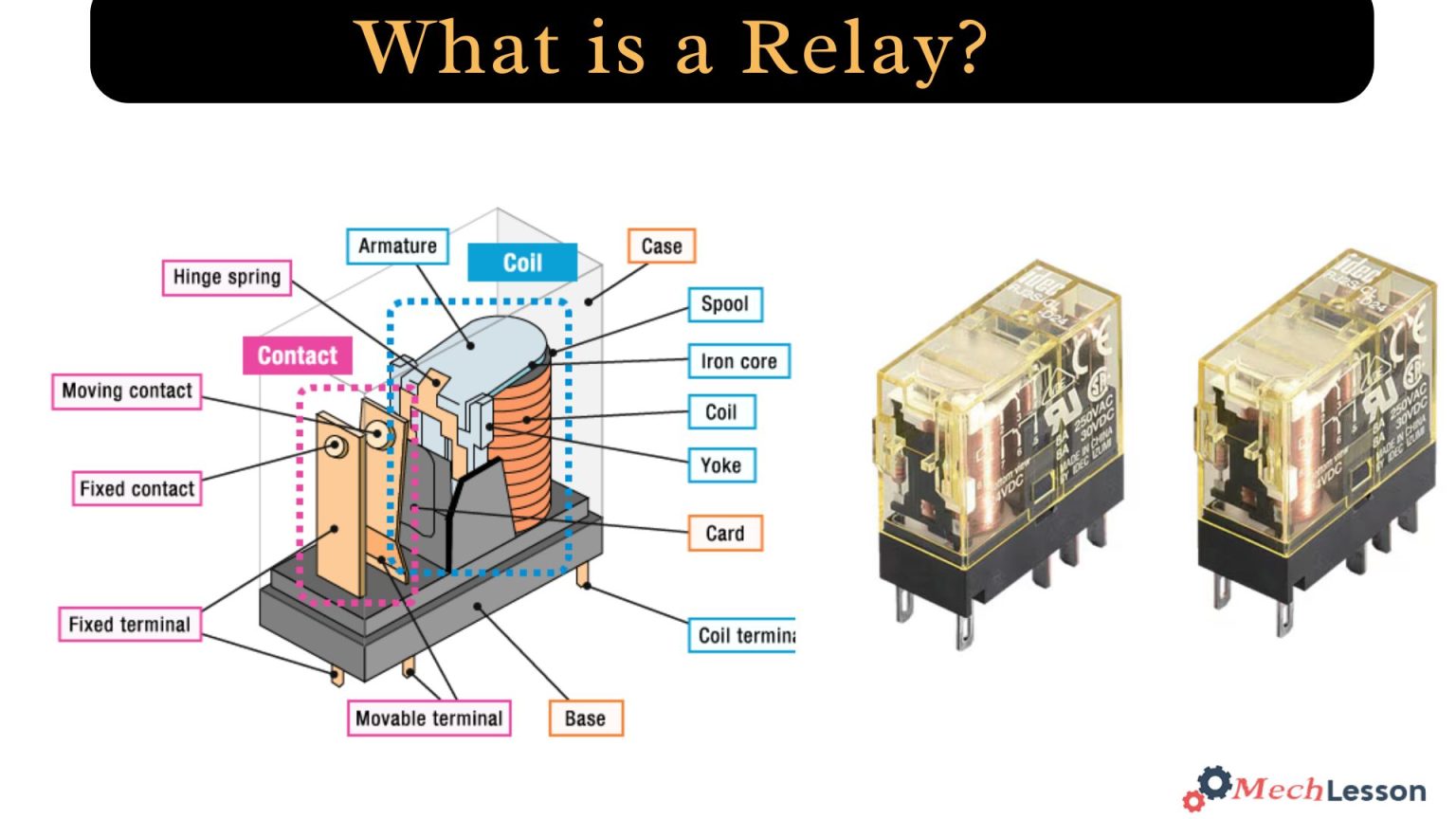
Frame – a container or heavy-duty frame that contains and supports the various parts of the relay.
Coil – is a wire wound around a metal core. It’s the part that causes an electromagnetic field
Armature – is a moving part that opens and closes the contacts. The armature can be moved back to its starting position using the spring that is attached.
Contacts – it’s the conducting part that causes the relay to make (close) or break (open) a circuit.
Relays have two circuits: an energy circuit and a contact circuit. The energising side has the coil, while the relay contacts have the contact side. The current flows through a relay coil, energising it and creating a magnetic field.
An AC unit undergoes 120 polarity changes per second, while a DC system maintains a fixed polarity.
A magnetic coil attracts a ferrous plate, a part of the armature. The armature is attached to the metal frame, which allows it to pivot. The other end opens and closes the contacts, which come in different configurations.
These configurations depend on the number of the relay’s breaks, poles, and throws. For example, we can refer to a relay as either single-pole, single-throw (SPST) or double-pole, single-throw (DPST).
Break:
A break is the number of separate places or contacts that a relay uses to open or close a single electrical circuit. These contacts are either single or double-break; a single-break contact (SB) breaks an electrical circuit in one place. A double-break contact (DB) breaks an electrical circuit in two different places.
Normally, we use a single break contact to switch lower-power devices like indicating lights. A double break contact is used when switching high-power devices like solenoids.
Pole:
A pole refers to multiple isolated circuits that a relay can transfer through a switch. A single-pole contact (SP) can carry current through only one circuit at a time. On the other hand, a double-pole contact (DP) has the ability to simultaneously carry current through two isolated circuits.
Well, the maximum number of poles a relay can carry is 12, depending on its design.
Throw:
A throw is the number of closed contact positions per pole that are available on a switch. A single-throw switch can control only one circuit, while a double-throw can control two.
In simple terms, an electromagnetic relay is made up of a wire coil around a soft core, an iron piece that helps direct magnetic flow, a movable iron part, and one or more sets of switches.
Diagram
Types of relays
Below are the various types of relays used and suitable for different applications:
Latching relays:
Relays of the latching type maintain their state after actuation. This characteristic is why they are also called impulse relays, keep relays, or stay relays. It’s used in most applications to limit power consumption and dissipation.
Internal magnets in latching relay types hold the contact position when current flows to the coil. With this, the system requires no power to maintain its position.
This is why, after being actuated, it manages to maintain the last contact position even if the current is removed from the coil.
Solid-state relays (SSRs):
Solid-state types of relays use components such as BJTs, thyristors, IGBTs, MOSFETs, and TRIACs. These components carry out switching operations.
Compared to electromagnetic relays, the power obtained in solid-state relays is much higher because the power needed to control the circuit is much lower. These relays can work for both AC and DC supply.
Solid-state types of relays have high switching speeds since there are no mechanical contacts. There is a sensor in a solid-state relay, which is also an electronic device. This sensor helps to switch on or off the power to the load after responding to a control signal.
Reed relays:
Similar to electromagnetic relays, reed relays function by mechanically actuating physical contacts to open or close a circuit path. However, the reed relays have low mass and much smaller contacts compared to the electromagnetic types.
The reed switch is wound as it acts as an armature. It’s a glass tube or capsule filled with an inert gas contained in two overlapping reeds or ferromagnetic blades, which is hermetically sealed.
Coaxial relay:
A coaxial relay is frequently used as a TR (transmit-receive) relay in situations where radio receivers and transmitters share a single antenna to move the antenna from the reception to the transmitter.
This procedure isolates the receiver from the strong transmitter signal. Transceivers that combine the transmitter and receiver into one device frequently employ such relays.
The relay connections are made to offer extremely high isolation between the receiver and transmitter terminals and not to reflect any radio frequency power toward the source.
The transmission line impedance of the system, for instance, 50 ohms, is matched to the characteristic impedance of the relay.
Differential relays:
Differential types of relays start working when the phasor difference of two or more similar electrical quantities exceeds a predetermined value.
Current differential relays operate when the system experiences a comparison between the magnitude and phase difference of the currents entering and leaving the system to be protected.
If the system is working at normal operating conditions, currents entering and leaving are equal in magnitude and phase. This condition causes the relay to be inactive. But if a fault occurs in the system, the currents are no longer equal in magnitude and phase.
Polarised relay:
The polarised types of relays, as their name suggests, are highly sensitive to the direction of the current that powers them. It’s a DC electromagnetic relay provided with an additional source of a permanent magnetic field to move the armature in the relay.
Permanent magnets, electromagnets, and an armature construct magnetic circuits in polarised relays. Instead of spring force, these types of relays use magnetic force to attract or repel the armature.
This armature is a permanent magnet, positioned between the pole faces formed by an electromagnet.
Buchholz relays:
The Buchholz types of relays are gas-operated or actuated relays. We widely use them to detect incipient faults or internal faults, which may initially be minor but have the potential to become major over time.
These relays are mostly used for transformer protection, and they are mounted in a chamber between the transformer tank and conservator.
Only oil-immersed relays, specifically designed for power transmission and distribution systems, use these relay types. The figure below shows the workings of a Buchholz relay.
Inverse definite minimum time relays (IDMT Relays):
Inverse definite minimum time relays are types of relays that offer definite-time current characteristics of a fault current at a higher value. And also, an inverse time-current characteristic of a fault current at a lower value.
We widely use these IDMT relays to protect distribution lines and to set limits for current and time settings. In these types of relays, their operating time is approximately inversely proportional to the fault current near the pickup value.
Protective Relay:
In electrical and power distribution systems, protective relays are used to identify faults, deviations, and overloads and to initiate preventative measures like power cuts or alarms.
Overload protection relays:
Relays designed specifically for overload protection provide overcurrent protection for electrical motors and circuits. These overload relays are of different types, such as fixed bimetallic strip type, electronic or interchangeable heater bimetallic, etc.
When an electric motor experiences overload, it necessitates the use of these types of relays to safeguard the system against overcurrent. For this reason, overload sensing equipment such as a heat-operated relay must be employed.
This heat-operated relay contains a coil that heats a bimetallic strip or solder pot, which then melts.
Relay Test
Relays are electromechanical devices; therefore, they ultimately wear out and quit functioning. However, there are a few methods to determine whether a relay is operational or not. These methods consist of:
- Using a Multimeter to Test a Relay
- Make a straightforward circuit to test the relay.
- To check whether a relay is operating properly, use a DC power supply.
Related: How To Test a Relay In Few Simple Steps
Working principle
The working principle of an electrical relay depends on its type and what it’s designed to do. However, a simple electromagnetic relay consists of a coil of wire wrapped around a soft iron core (a soft iron core).
It also contains an iron yoke that provides a low reluctance path for magnetic flux, a movable iron armature, and one or more sets of contacts.
The yoke hinges this armature, mechanically connecting it to one or more sets of moving contacts. A spring helps to hold the armature in place so that when the relay is de-energised, there is an air gap in the magnetic circuit.
Some relay types have one set of contacts closed and the other set open.
Some relays may have more or fewer sets of contacts depending on their purpose of use. There is a wire connecting the armature to the yoke, which ensures continuity of the circuit between the moving contacts on the armature.
When an electric current passes through the coil, it generates a magnetic field that activates the armature, and the consequent movement of the movable contacts either makes or breaks a connection with a fixed contact.
If the set of contacts was closed when relays were de-energised, then the movement opens the contacts and breaks the connection, and vice versa if the contacts were open.
When the current to the coil is not energised, the armature is returned to its relaxed position by a force approximately half as strong as the magnetic force. Industrial motor starters typically use a spring to provide the force, but they also use gravity.
Selection considerations of a relay
Below are factors to be considered while selecting a relay for a system:
- Protection: While selecting a relay for a specific project, one must consider how it will protect the system from overloads or sudden power spikes. Some other protection, such as contact protection and coil protection, must be considered. Contact protection will help reduce arcing in circuits with inductors. During switching, coil protection helps lower the surge voltage.
- Consider standard relays that have received all regulatory approvals.
- High-speed switching relays are vital for the switching time; you might need one.
- Consider the relay’s current and voltage ratings. The current ratings vary from a few amperes to about 300 amperes, whereas the voltage ratings vary from 300 volts AC to 600 volts AC. Some high-voltage relays of about 15,000 volts are also available.
- Isolation between a coil circuit and contacts should also be considered.
- Know the types of contact it carries, whether it’s NC, NO or closed contact.
- Know whether “Make Before Break” or “Break Before Make” contact is the best option for your system.
Related: Car Starter Not Engaging: Causes and How to Diagnose the issue
Advantages
Below are the advantages of various types of relays:
- It allows a remote device to be controlled.
- Contacts are changing easily.
- Isolates activate a part of an actuating part.
- It works well at high temperatures.
- It can be activated with a low current and can activate large machines of great power.
- A single signal can be used to control several contacts at once.
- Direct current or alternating current can be a switch.
Disadvantages
- Contacts in the system damage over time. It often experiences wear, oxidation, etc.
- Switching time is high
- Sounds of activation and deactivation of contacts can be disturbing.