A cruise control system is comparable to the governor system. It keeps your car, lawnmower or other outdoor power equipment running at a steady pace. Properly calibrated governors maintain your speed independent of engine load or the amount of work the engine has to do.
Well, in this reading, we’ll explore what an engine governor is, its functions, diagrams, and types. I will also explore the advantages and disadvantages of governors in an engine.
Let’s begin!
Learn about Causes, Symptoms and Solution of a Car Engine Overheating with this detailed guide!
What is Engine Governor?
An engine governor is a mechanism that, when carried out of load, automatically keeps an engine or other prime mover’s rotating speed within acceptable bounds. Typically, a governor modifies the rate at which fuel is supplied to an engine to control its speed.
Almost all governors rely on centrifugal force to operate. They are made up of two masses that rotate around a spindle that is powered by the prime mover and prevented from flying outward by a regulating force, often springs.
A centrifugal governor, sometimes referred to as the Watt or fly-ball governor on a reciprocating steam engine, is a classic example of a governor, also known as a speed limiter or controller.
This modulates the input flow of steam by using the effect of inertial force on rotating weights driven by the machine output shaft. The regulating force is overcome as speed increases, causing the masses to move outward. This movement is relayed to the valves that feed the prime mover with fuel or working fluid.
The revolving masses are balls that are connected to a vertical spindle by link arms; the weight of the balls acts as the regulating force.
The engine load of a mower can be impacted by the height of the grass or slopes. While the thickness of the branches may have an impact on a chipper’s load, the depth of the tines may determine the load for a tiller engine.
Functions
- It regulates engine mean speed based on load variations.
- The system Increased load decreases engine speed, necessitating increased working fluid supply.
- It decreased load, increasing engine speed, necessitating less working fluid.
- The governor automatically controls fluid supply to maintain engine mean speed.
- The governor configuration changes with load increase, adjusting working fluid supply.
Diagram
Learn about 38 Parts Of a Car Engine And Diagram with this detailed guide!
Types Of Car Engine Governor
The following are the three different types of governors used in automobile vehicles:
- Centrifugal governor
- Inertia Governor
- Hydraulic governor
Centrifugal Governor
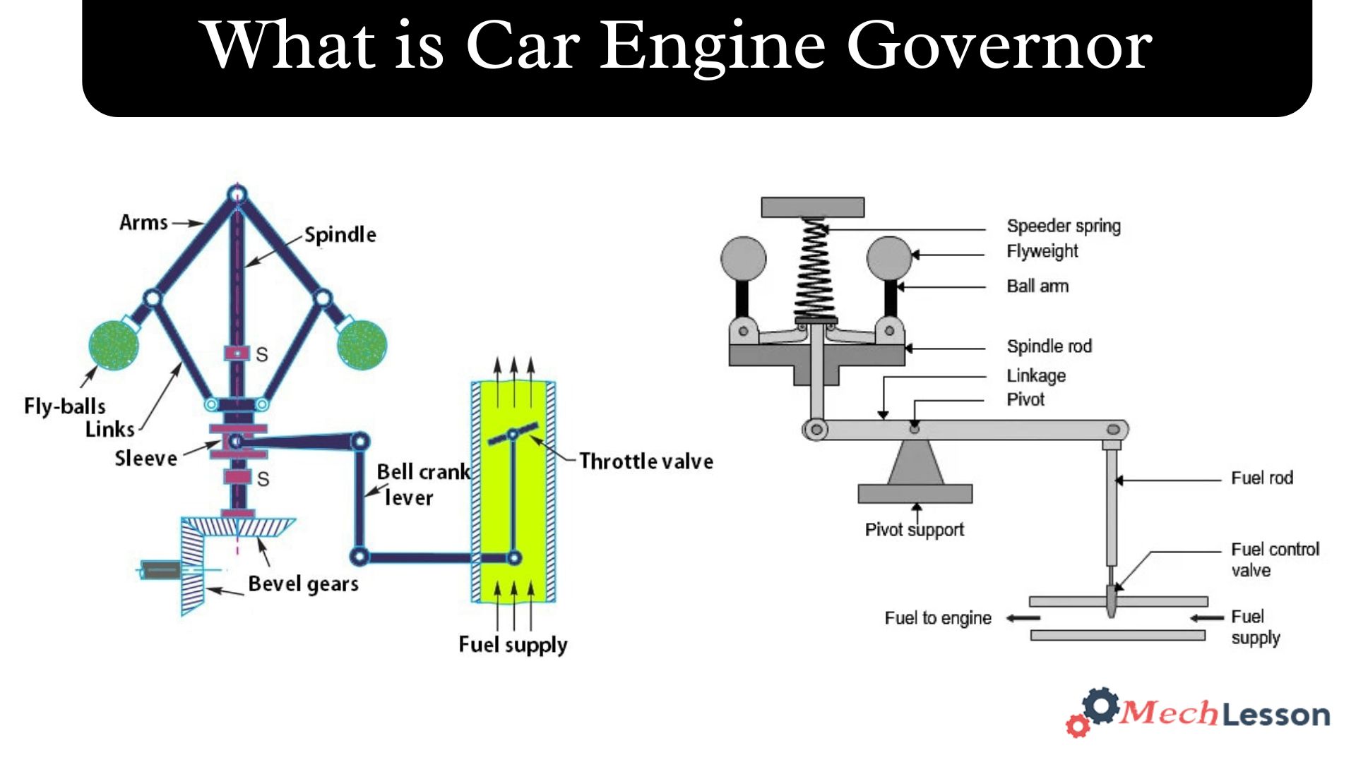
The foundation of centrifugal governors is the equal and opposite radial force, referred to as the regulating force*, which balances the centrifugal force acting on the revolving balls. It is made up of two equal-mass balls fastened to the arms.
These balls are referred to as fly balls or governor balls. Through bevel gears, the engine powers a spindle that rotates the balls. The balls can rise or fall as they rotate around the vertical axis since the top ends of the arms are pivoting to the spindle.
Governor of the Engine, these are the connections to a sleeve that is keyed to the spindle to connect the arms. This sleeve can move up and down, but it revolves with the spindle. When the spindle speed rises, the balls and sleeves rise, and when the speed declines, they descend.
Two stops, S, S, are supplied on the spindle to restrict the sleeve’s upward and downward motion. A bell crank lever connects the sleeve to a throttle valve. When the sleeve rises, the working fluid supply diminishes, and when it falls, it increases.
Both the engine and the governor speed decrease as the engine load increases.
As a result, the balls experience less centrifugal force. As a result, the sleeve slides lower, and the balls migrate inside. A throttle valve at the other end of the bell crank lever is opened by the sleeve’s downward movement, increasing the working fluid supply and, consequently, the engine speed.
In this instance, the higher load is balanced by the additional power production. Centrifugal force on the balls increases when the engine and governor speed rise in response to a drop in engine load.
The sleeve rises higher as a result of the balls moving outward. Because the sleeve is moving upward, less working fluid is available, which lowers speed. The power output is decreased in this situation.
Learn about Engine Antifreeze and Coolant Fluids with this detailed guide!
Inertia Governor
Inertia governors, also known as flywheel governors, work on the basis of the law of inertia. They make use of a weighted lever or pendulum mechanism that uses the spinning parts’ inertia to react to variations in speed. The inertia governor modifies the control systems to maintain a constant speed as the speed rises or falls.
Because they work on a distinct principle, inertia governors are very different from centrifugal governors. The arrangement of the governor balls in an inertia governor tends to change their locations due to the inertia force produced by the angular acceleration of the governor shaft.
A spring and a mechanism inside the governor control the balls’ displacement, which in turn controls the air-fuel mixture’s delivery. The rate at which the governor shaft’s speed changes determines the locations of the balls in an inertia governor. As a result, these governors react quickly to variations in load.
Inertia governors function in response to acceleration, as opposed to centrifugal governors, which react to limited changes in speed. However, because it is practically difficult to arrange and achieve the desired balance of the rotating elements in inertia governors, centrifugal governors are typically favoured over inertia governors.
Centrifugal governors are a more popular option in many situations because inertial governors can be more difficult to develop and execute.
Hydraulic Governor
High mechanical forces required to support loads and potential torsional vibrations in the drive are eliminated by hydraulic governors. Therefore, they are preferred over governors that are mechanical.
The centrifugal force that controls speed is the operational agent in a mechanical governor. It is the pressure differential across an opening that is necessary in a hydraulic governor to allow oil flow from an engine-driven positive oil pump. The square of the engine speed determines the variation in the pressure differential.
Additionally, the driver’s foot pressure on the accelerator pedal determines its balance. Similar to a mechanical governor, a hydraulic governor functions as an all-speed governor, meaning that it controls the entire rack and does not rely on the accelerator to maintain speed, regardless of the power requirements at any given time.
Advantages
Using a governor in an engine has the following benefits:
- Speed Regulation: By regulating the working fluid supply, the governor helps the engine run steadily under a range of load circumstances by maintaining a constant mean speed.
- Increased Efficiency: The governor maximises the engine’s fuel consumption and efficiency by managing the working fluid supply, which improves performance all around.
- Prevents Overspeeding: By restricting the working fluid flow, it keeps the engine from operating at excessively high rates, perhaps preventing harm to the engine.
- Load balancing: The governor ensures that the engine runs smoothly and without undue strain by assisting in balancing the load on it.
- Self-Regulation: The governor operates on its own without continual human intervention, which eliminates the need for ongoing supervision.
Learn about List Engine Air Filter with this detailed guide!
Disadvantages
- Limited responsiveness: Some governor types may react slowly to abrupt changes in load, which can result in brief variations in engine speed.
- Mechanical Complexity: Governor systems have the potential to complicate engine setup, which might result in a greater need for maintenance and repairs.
- Electricity Loss: Because the governor requires a little amount of electricity to operate, the engine’s overall output is somewhat reduced.
- Sensitivity to Wear and Tear: Over time, the governor’s accuracy and functionality may be impacted by wear on its constituent parts.
- Incompatibility with Modern Controls: The employment of sophisticated engine management technologies may be restricted by earlier governor designs’ poor integration with contemporary engine control systems.
FAQs
What is the function of the engine governor?
The governor’s purpose is to control the fuel to the engine cylinders so as to control the speed of the unit, holding the speed constant for all conditions of load imposed on the generator being driven by the engine.
What is governing in an engine?
The governing system monitors the speed and load on the unit and regulates the fuel injection system to attempt to hold the speed or load on the unit constant. We will explain how this is done in several different systems that are used on diesel engines in nuclear plant applications.
What is engine-governed speed?
Governed engine speed, or “maximum governed rpm,” means the maximum engine speed obtainable when the [diesel] engine is driving the vehicle under a loaded condition, as specified by the engine manufacturer.
What causes a governor to fail?
- The oil supply of each cylinder is uneven.
- Carbon or oil drips from the hole in the fuel injection nozzle.
- The connecting pin of the gear rod is loose.
- The axial clearance of the injection pump camshaft is too large.