
Chip formation is the process in which material is mechanically removed from a workpiece during cutting operations, creating chips. These chips can be classified into different types based on their characteristics, including continuous, discontinuous, and continuous with a built-up edge.
In this reading, we’ll explore what chips are, how they’re formed, the diagram of chip formation, and the types of chips. We’ll also learn factors affecting chip formation.
What Are Chips?
Chip is a byproduct of mechanically cutting materials with equipment like milling cutters, lathes, and saws. World War II and the introduction of quicker and more powerful cutting tools, especially high-speed steel cutters for metal cutting, motivated research on the subject of chip formation. Both Franz (1958) and Kivima (1952) conducted groundbreaking research in this area.
How Are Chips Formed?
When a cutting tool (like a lathe, saw, or milling cutter) interacts with a workpiece, the tool’s cutting edge deforms the material, causing it to shear and separate, resulting in the formation of chips.
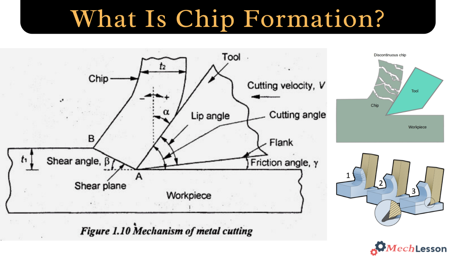
Diagram Of Chip Formation

Types Of Chips
In machining, the type of chip produced depends on factors like the workpiece material, cutting speed, feed rate, and tool geometry. The main types of chips in machining are:
Continuous Chip
Continuous chips form a ribbon-like coil with the same thickness. Cutting ductile materials like low carbon steel, copper, brass, and aluminum alloys at high cutting velocities and tool cutting edge pressure in compression and shear forms this chip. This puts material before the tool’s edge. Chip formation is also aided by sharp cutting edges and low tool-chip friction.
Prior to the cutting edge is the principal deformation zone. Work material deforms in the secondary deformation zone due to friction at the tool-chip contact. This zone’s thickness is related to friction. Surface distortion arises when cutting soft metals at low speed and rake angles. It yields poor soft metal machining results.
Continuous chips produce smooth cutting and superior surface quality. Increases tool life and reduces power use. The cutting tool has chip breakers to prevent chips from tangling. This frequently occurs during turning.
Discontinuous Chip
Brittle materials like cast iron, bronze, and high carbon steel produce discontinuous chips when machined at moderate speeds. These parts are loosely connected. The material loses ductility and fractures during strain, and chip flow ruptures periodically.
Cutting forces change often during chip formation. This chip is made due to high tool-chip friction, a large feed, and a depth of cut. Discontinuous chips degrade tool life and surface finish when cutting ductile materials.
In discontinuous chip formation, cutting tool and holding device stiffness can cause vibration, dimensional inaccuracy, poor surface finish, and cutting tool damage. Due to their small length, discontinuous chips are easier to handle than continuous chips. It is also disposable.
Continuous Chip With Built-Up Edge
During cutting, high friction between tool-chip interfaces causes chip material to fuse to the tool rake surface at the tooltip, creating a build-up edge. It can be severe if the chip constantly touches the tool. Consider it as an extension of the tool’s edge. A temporary and unstable buildup edge forms.
Machining removes its pieces. The chip and machined surface may stick partially after machining. It causes poor surface finishing. However, it offers a poor surface finish, decreases tool wear and enhances tool life by adding a coating over the cutting edge.
Segmented or serrated chip
A different term for serrated chips is non-homogeneous chips. A large zone of high shear strain followed by a small zone of low shear strain gives this chip a sawtooth appearance. This cyclic chip creation makes it semi-continuous. These chips form when machining hard materials like titanium alloys, nickel-based superalloys, and austenitic stainless steel at high speeds.
Classification Of Chips
In the mid-1900s, American engineer Dr. Norman Franz studied chips in manufacturing and identified three primary classifications. Most chips, according to Franz, fall into one of the three classifications:
Type I chip
Type I chips are formed when a material breaks ahead of the cutting edge due to the tool’s upward wedge action exceeding the substance’s perpendicular tensile strength. They are crucial in fibrous materials like wood, whose fibers are strong yet easily separated.
Type I chips are typically formed when cutting with tools that have shallow cutting angles. Only the cut length limits the size of type I chip swarf. This is the optimal chip structure for wood shavings, especially those from a well-tuned plane with a fine mouth.
Type II chip
Type II chips form when the tool angle wedge shears. The material fails in a short inclined plane from the tool edge’s apex, diagonally upwards and forwards to the surface. Deformation along this line creates an upward curling chip. Usually, these chips are created by cutting at intermediate angles. A ductile material like metal can create Type II chips. Type II chips can also generate continuous swarf.
Type-III chip
Type III chips cause material compression failure before a 90° cutting angle. This can make a fine dust chip in weak or non-ductile materials, but it often creates a random “snowplough” effect when waste material is bunched up ahead of the tool but not swept away.
This type of chip is formed by routers. Woodworking scrapers often generate a thin Type III chip that looks like a Type II chip when properly sharpened and utilized. Thin waste chip reduces compression failure volume to match Type II’s well-defined shear plane.
Factors Affecting Chip Formation
There are several factors that affect chip formation, including:
- Material properties: Ductile materials tend to form continuous chips, while brittle materials form discontinuous chips.
- Cutting speed and feed rate: Higher speeds and feed rates can lead to continuous chip formation, while lower speeds and feed rates can lead to discontinuous chips.
- Tool geometry: The angle and sharpness of the cutting tool’s edge can significantly impact chip formation.
- Lubrication and cooling: Using lubricants and coolants can reduce friction and temperature, which can affect chip formation.
- Workpiece temperature and hardness: These factors can also influence the type of chip formed.
- Tool material and coatings: The type of material used for the cutting tool and any coatings it may have can affect chip formation.