

A gear is a type of machine component where teeth are evenly spaced around cylindrical or cone-shaped surfaces. by combining two of these components.
The most typical uses for gears and gear trains are to switch the axis of rotation, flip the sensation of rotation, and exchange torque for rotational speed between two axles or other rotating components.
Well, in this reading, we’ll explore what a gear is, its applications, parts, diagram, mechanism, types, design, and how it works. We’ll also explore its advantages and disadvantages.
Let’s begin!
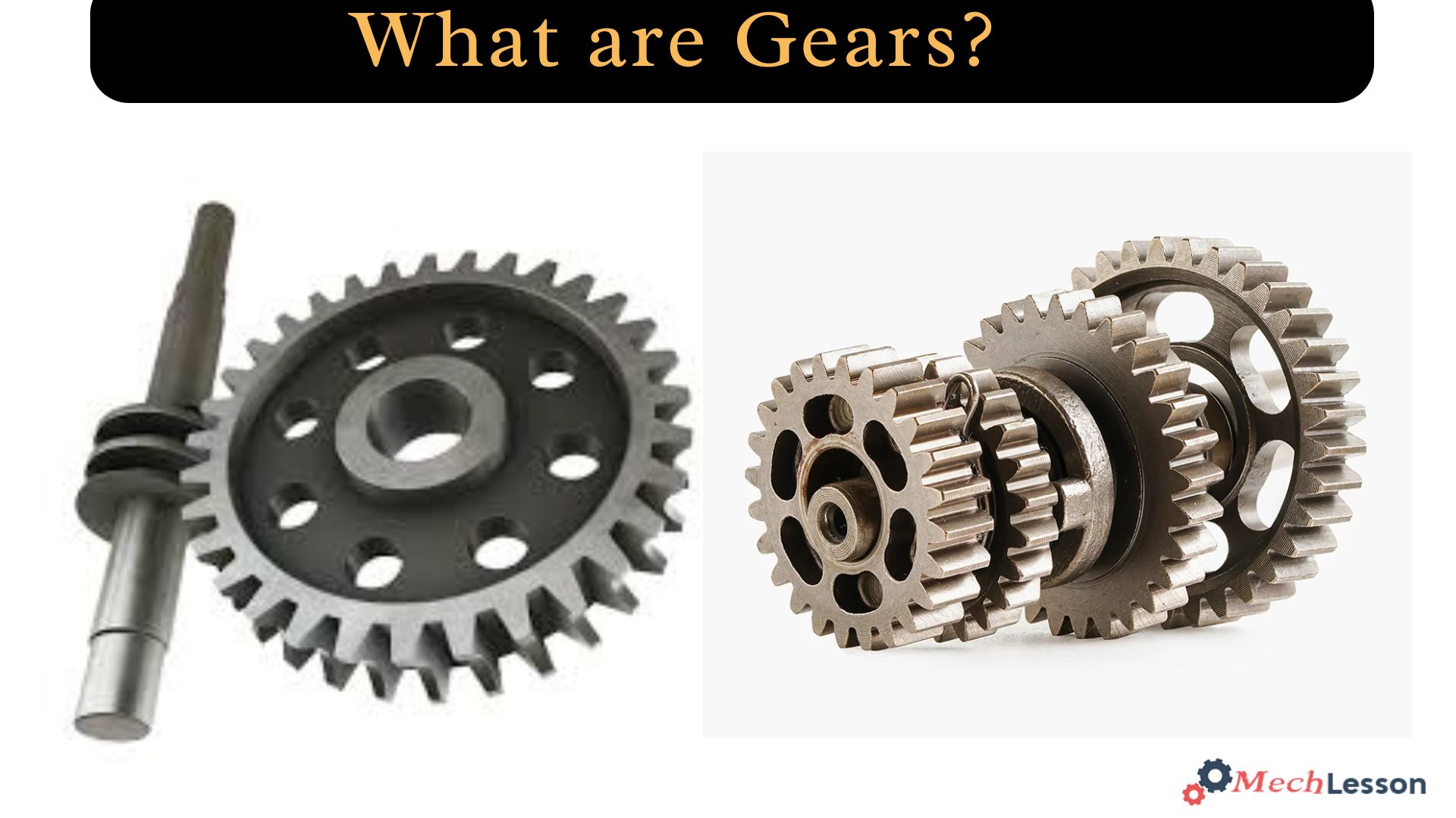
What are Gears?
Gears are a type of machine component where teeth are evenly spaced around cylindrical or cone-shaped surfaces.
Rotations and forces are transferred from the driving shaft to the driven shaft by meshing two of these components. Involute, cycloidal, and trochoidal gears are the three shapes into which gears fall.
A gear, or gearwheel, is a revolving machine component that is usually used to transfer torque and/or rotational motion through a set of teeth that mesh with the teeth of another gear or component.
The teeth may be machined into the component as inherent saliences or cavities, or they may be inserted as separate pegs. The gear in the latter instance is typically referred to as a cogwheel.
One of the pegs or the entire gear might be a cog. Gear trains are made up of two or more meshing gears.
Additionally, they can be categorised as parallel, intersecting, non-parallel, and non-intersecting shaft gears based on their shaft locations. Gears have a long history, and Archimedes’ writings from ancient Greece in B.C. mention their use.
This is to say, gears are mechanical components that transmit rotation and power from one shaft to another if each shaft possesses appropriately shaped projections (teeth) equally spaced around its circumference such that as it rotates, the successive tooth goes into the space between the teeth of the other shaft.
Related: What is Hypoid GearBox? Its Diagram and How it Works
Applications
Below are the major applications of gears:
- Gears are essential for the transmission of motion and power in various industries.
- They are designed to reduce or increase speed in motorized implements and change the direction of power smoothly and efficiently.
- Gears are made from highly durable materials and play a key role in machine productivity and manufacturing operations.
- Gears regulate power by their ratios, with different sizes used to increase or decrease transmitted power.
- Gears intermesh with other gears without slipping and retain their connections during power transmission.
- Motors use gears to transmit power to the shaft to power a tool.
- Torque is the rotating force produced by motors and engines, adjusted through gears, gear sets, gearboxes, and gear assemblies.
- Smaller gears produce less torque, while large gears produce higher amounts of torque.
- Gears are used to change the direction of rotation or movement, completed by the specific design of gear pairs.
- Gearboxes are a foundational part of motor-driven vehicles and gas-powered machinery.
- Bevel gears are typically used for applications where gears intersect at a right angle, but are more costly and transmit less torque compared to parallel shaft gear arrangements.
Parts of Gears
The major parts of a gear include the axis, teeth, pitch cycle, pitch diameter, diametrical pitch, circular pitch, module, and pressure angle.
Gears are designed to transmit rotation through a series of jagged faces, known as teeth. The number of teeth on a gear is an integer, and they must mesh and have the same profile.
The pitch circle defines the size of the gear, and two intermeshing gears must be tangential for intermeshing. The pitch diameter is the working diameter of the gear, and the sum of two pitch diameters divided by 2 corresponds to the distance between the two axes.
The diametrical pitch is the ratio of the number of teeth to the pitch diameter, and two gears must have the same diametrical pitch to mesh. The circular pitch is the distance from a point on one tooth to the same point on the adjacent tooth, measured along the pitch circle.
The module of a gear is the circular pitch divided by pi, which is easier to handle than the circular pitch.
The pressure angle of a gear is the angle between the line defining the radius of the pitch circle and the point where the pitch circle intersects a tooth. Standard pitch angles are 14.5, 20, and 25 degrees.
Gear Drawing and Diagram
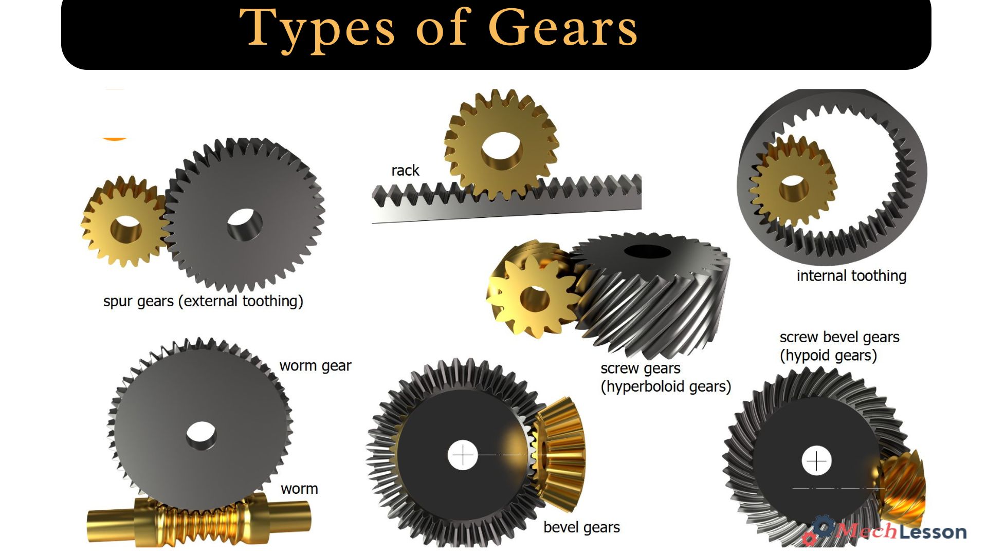
Types of Gears
The popular types of gears include:
- Spur Gear
- Helical Gear
- Gear Rack
- Bevel Gear
- Spiral Bevel Gear
- Screw Gear
- Double Helical Gear
- Herringbone Gear
- Hypoid Gear
- Miter Gear
- Worm Gear
- Internal Gear
Spur Gear
The gear types having cylindrical pitch surfaces are known as cylindrical gears. Spur gears are parallel shaft gear group and are cylindrical gears with a tooth line that is straight and parallel to the shaft.
Spur gears are the most commonly used gears that can achieve great precision with relatively easy manufacturing methods. They have the attribute of being unloaded in the axial direction (thrust load).
The bigger of the meshing pair is called the gear, and the smaller is called the pinion.
Helical Gear
These types of gears are cylindrical gears with winding tooth lines that are used with parallel shafts, much like spur gears. They are suitable for high-speed applications because they can transmit heavier weights, are quieter, and have better teeth meshing than spur gears.
Thrust bearings are required when using helical gears since they generate thrust force in the axial direction. For a meshing pair, helical gears need opposite hand gears since they have right and left hand twists.
Gear Rack
A gear rack is made up of teeth of the same size and form that are cut at equal intervals along a straight rod or a flat surface.
A gear rack is known as a cylindrical gear with an infinite pitch cylinder radius. It transforms rotational momentum into linear motion by meshing with a cylindrical gear pinion.
Although they both contain straight tooth lines, gear racks can be roughly classified as either helical or straight tooth racks. It is easy to join gear racks end to end by cutting their ends.
Bevel Gear
The bevel gears are a type of gear that resembles cones. Its purpose is to transfer force between two shafts that cross at a single point. The teeth of a bevel gear are carved along the cone that serves as its pitch surface.
Straight bevel gears, helical bevel gears, spiral bevel gears, mitre gears, angular bevel gears, crown gears, zerol bevel gears, and hypoid gears are among the several types of bevel gears.
Spiral Bevel Gear
Bevel gears with curved tooth lines are known as spiral bevel gears. They outperform straight bevel gears in terms of strength, vibration, noise, and efficiency because of their greater tooth contact ratio.
However, these types of gears have a complex design, making their production more challenging. Additionally, the teeth generate thrust forces in the axial direction due to their curve. Zero bevel gears are those that have zero twisting angles among spiral bevel gears.
Screw Gear
Screw gears are two identical helical gears on non-parallel, non-intersecting shafts having a 45° twist angle. They have a poor load-bearing capability and are not appropriate for high-power gearboxes since the tooth contact is a point.
When employing screw gears, lubrication must be considered since power is transferred by the tooth surfaces sliding. Regarding the combinations of teeth, there are no limitations.
Miter Gear
Bevel gears having a speed ratio of one are called mitre gears. They are employed to change the power transmission’s direction without altering its velocity. Spiral and straight mitre gears are two types available.
Since thrust bearings generate thrust force in the axial direction, they must be taken into consideration when employing spiral mitre gears. In addition to the standard mitre gears with shaft angles of 90°, angular mitre gears are mitre gears with any other shaft angle.
Worm Gear
A screw-shaped cut on a shaft is the worm, the mating gear is the worm wheel, and together on non-intersecting shafts is called a worm gear. Worms and worm wheels are not limited to cylindrical shapes.
There is the hourglass type, which can increase the contact ratio, but production becomes more difficult. Due to the sliding contact of the gear surfaces, it is necessary to reduce friction.
For this reason, generally a hard material is used for the worm, and a soft material is used for the worm wheel. Even though the efficiency is low due to the sliding contact, the rotation is smooth and quiet. When the lead angle of the worm is small, it creates a self-locking feature.
Internal gear
Internal gears are coupled with exterior gears and have teeth carved on the inside of cylinders or cones. Planetary gear drives and gear-type shaft couplings are the primary applications for internal gears.
Mechanism and Design
Gears are essential components in industrial applications, with their design varying based on various factors such as shape, tooth design and configuration, and axis configuration. Circular gears provide a consistent gear ratio, while non-circular gears result in variable gear ratios.
Gear teeth are crucial characteristics of a gear, influenced by factors such as tooth structure, placement, and profile. Teeth can be cut directly into the gear or inserted separately, and their placement determines rotational direction.
Tooth profiles, such as involute, trochoid, and cycloid, affect speed and friction in the gear. Involute gears have a curve that forms a locus shape, providing constant pressure and consistent performance.
Trochoidal gears are often used in pumps, while cycloidal gears are employed in pressure blowers and clocks.
Gear axis configuration is based on the positional relationship of their axes and gear pairs. The three main classifications are parallel axis, intersecting axis, and non-parallel/non-intersecting axis.
In parallel axis configurations, shafts are aligned parallel to each other, while in intersecting axes, shafts are positioned at an angle or perpendicular to each other. Non-parallel and non-intersecting gears transmit rotational force through slippage between gear tooth surfaces.
Parallel axis gear configurations involve power transmission between parallel shafts, creating rolling contact for efficiency levels of 98% to 99.5%. Common types of gears used for this configuration include double helical, helical, herringbone element, and spur gears.
Helical gears are better choices for high torque applications due to their angled teeth and quieter operation. Parallel axis configurations offer excellent reliability, ease of maintenance, and a minimal number of components.
The gear configuration plays a crucial role in determining the efficiency and effectiveness of a system. Intersecting gear configurations feature two axes that cross at a single point within the same plane, ensuring proper alignment and maintenance of the pinion axis rotation.
These gears are housed in a gear enclosure that supports the gear shafts and includes bores for their support.
Non-parallel and non-intersecting gears, such as skew bevel gears or spiral gears, are positioned at right angles to each other and do not intersect. They often involve helical gears with angled teeth placed perpendicularly to each other.
The worm gear system, which includes a worm gear and a spur gear, also has a non-parallel and non-intersecting configuration.
The hypoid gear configuration, a type of non-parallel and non-intersecting gear setup, features a pinion that meshes with a larger gear, causing the axes of the two gears to be offset.
When selecting gears for a specific application, factors such as the material used in gear construction, surface treatments, the number and angle of teeth, and the type of lubricant should be considered.
How Do Gears Work?
Gears operate in pairs, where the teeth of one gear engage with those of the other to prevent slipping. The torque and rotational speed generated by circular gear pairs are constant.
However, the ratio of speed to torque may change if the gears are not circular.
It is essential to accurately shape the gear profile in order to maintain continuous torque and speed. The smaller gear, called the pinion, will increase torque and decrease speed when it is the driving gear.
On the other hand, speed will rise and torque will fall if the pinion is on the driven shaft. It is important to place the shafts holding the gear pairs near to one another yet far enough apart.
Levers in the form of revolving shafts link gears. Transferring rotation or energy from one component to another is the main function of gears. It is possible to link several gears at once.
There are three main possible outcomes in gear systems, which include increasing speed, increasing force, and changing direction.
In order to keep synchronisation, when two meshed gears are used, one with 40 teeth and the other with 20, the smaller gear with 20 teeth will revolve twice as fast as the bigger gear with 40 teeth. Higher speed but less force for the smaller gear results from this.
The force will rise and the speed will decrease if the smaller gear has more teeth than the bigger one. This implies that greater force will be needed to spin the smaller gear.
One linked gear will revolve in a clockwise direction while the other rotates anticlockwise. Specialised gears made for this purpose are needed to alter the angles or rotational direction.
Advantages and Disadvantages of Gears
Gear drives offer a large range of speed and torque for the same input power, with more accurate timing than a chain system. They provide a positive drive, allowing for a large velocity ratio with minimal space.
Gears are mechanically strong, allowing for higher loads to be lifted. They are used for the transmission of large H.F., transmitting motion over small shaft centers, and transmitting torque.
They require only lubrication, requiring less maintenance. Gear systems can transmit motion between non-parallel intersecting shafts and have a long life, making them compact.
However, they are not suitable for large velocities, transmitting motion over large distances, and may cause permanent damage due to toothed wheel engagement.
Related: What is Overdrive in a Car? its Functions and How it Works
FAQs
What do you mean by gears?
Gears are mechanical devices used to transmit torque and motion between machine components. They come in various shapes and sizes, each suited for specific applications. These are fundamental components in mechanical engineering, widely used to transmit torque and motion across various machines and devices.
What are the 4 types of gears?
The four types of gears include:
- Spur Gear: The spur gear has a helix angle of 0°.
- Worm Gear: Worm gears are found in right-angle gearboxes. Worm gears undergo a pivoting action.
- Helical Gear: This is an angle-toothed gear.
What is the classification of a gear?
The most common way to classify gears is by category type and by the orientation of axes. Gears are classified into 3 categories; parallel axis gears, intersecting axes gears, and nonparallel and nonintersecting axes gears. Spur gears and helical gears are parallel axes gears. Bevel gears are intersecting axes gears.