Fluid coupling, like most engineering concepts, is somewhat of a mystery. A hydrodynamic device known as fluid coupling or hydraulic coupling transfers mechanical power by use of a transmission fluid.
The concepts of fluid dynamics are included in almost every contemporary creation. It’s difficult to find a groundbreaking technology that doesn’t employ it, from rocket propulsion to modern toilets. One of the most significant engineering products is fluid dynamics.
Well, in this reading, we’ll explore what fluid coupling is, its applications, parts, diagram, and working principle.
Let’s begin!
Learn about Coupling with this detailed guide!
What is Fluid Coupling?
A hydrodynamic or “hydrokinetic” device used to transfer rotational mechanical power is called a fluid coupling or hydraulic coupling. It has been used in place of a mechanical clutch in car gearboxes.
It is also widely used in industrial and marine machine drives, where regulated start-up without shock loading of the power transmission system and variable speed operation are crucial.
It is important to separate hydrokinetic drives like this one from hydrostatic drives like hydraulic pumps and motor combinations.
Fluid coupling was created by Dr. Hermann Föttinger, a German physicist. Since receiving a posthumous patent in 1950, his innovation has been used in a number of industrial processes.
Additionally, a fluid coupling is a system that, in the absence of mechanical engagement, creates a controlled amount of slip between the input and output, as well as between the drive and the buffer.
As a result, the fluid couplings provide the engineer with significant advantages in a variety of power transfer events.
Applications
A fluid coupling or hydraulic coupling transfers mechanical power by use of a transmission fluid. This mechanism is widely used in the automobile industry in place of a clutch in order to transmit energy from the motor to the wheels.
A clutch was no longer necessary with the development of fluid coupling. It emerged as the source of torque conversion required for automated gear shifts in automobiles. Fluid coupling has been used in the construction of every automated vehicle now on the road.
The invention is used to transmit energy in different industries today, which is why they are seen in applications like centrifugal fans, centrifugal pumps, conveyors, mixers, ball mills, crushers, etc.
Fluid couplings are also used in maritime propulsion systems as a propellant material. Fluid coupling is used in more than simply automobiles. Another significant advantage of fluid couplings is their use in rail transportation.
In Britain, diesel locomotives are equipped with a semi-automated power transfer system. Fluid couplings are used in this power transmission to enable the locomotives to change gears automatically while moving.
You should also learn about Transmission System with this detailed guide!
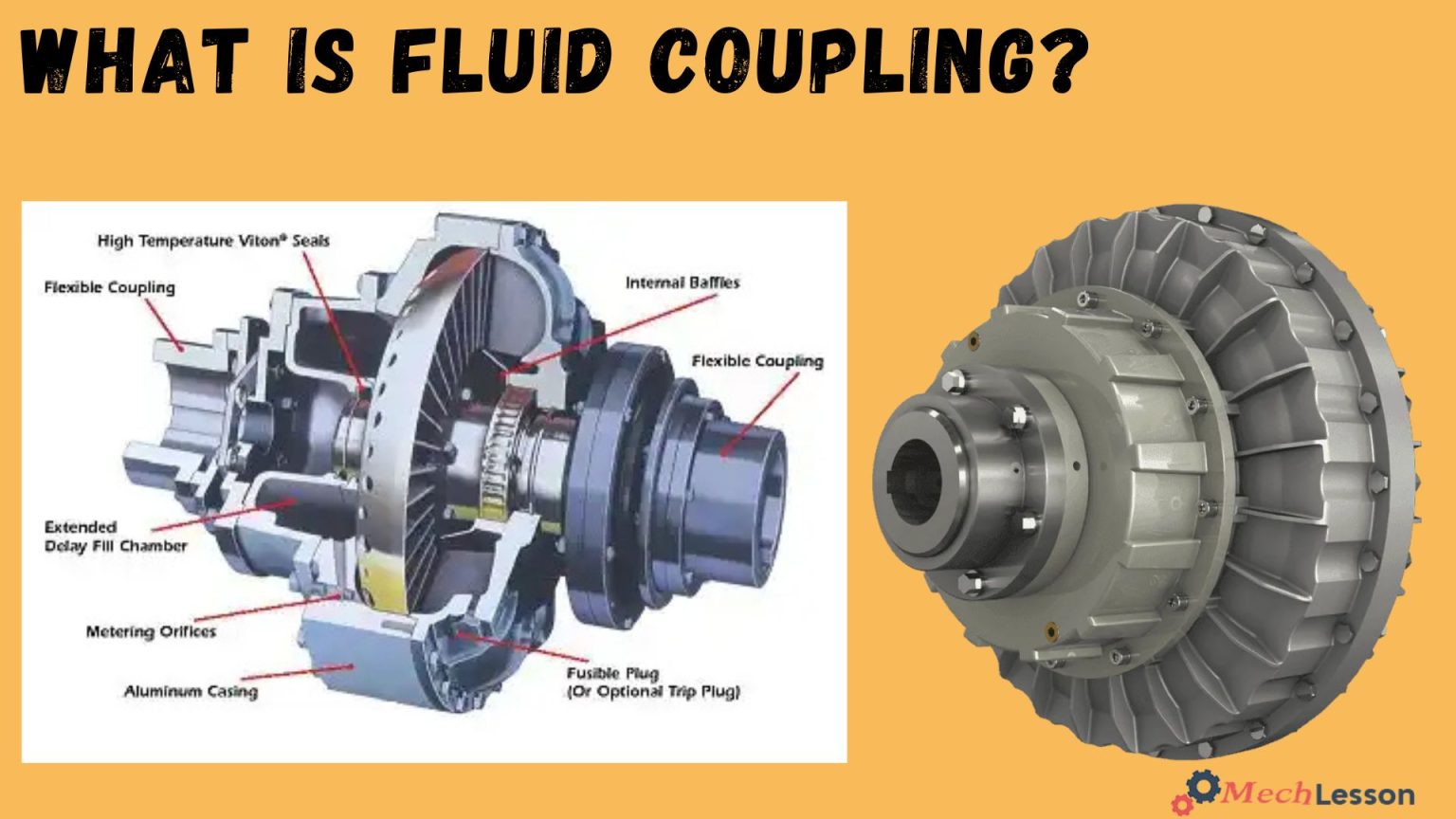
Parts and Diagram

You should learn about Torque Converter with this detailed guide!
How Does Fluid Couplings Work
Before the development of fluid coupling, every automobile had a manual gearbox. The clutch, which connects the engine and transmission, must be operated by the driver when using a manual transmission.
An automobile with a manual gearbox would stall every time it stopped without its clutch.
For the working principle of a fluid coupling, fluid dynamics and hydrokinetics serve as the foundation for fluid coupling theory. It differs greatly from hydrostatic systems, such as hydraulic pumps, because of this.
A fluid coupling is made up of two wheels with blades facing one another but not touching. An impeller, which is one wheel, is connected to a power source. The impeller supplies power to the other, known as the turbine, which then sends it straight to the transmission.
The turbine, which is the output, rotates more slowly than the impeller, also referred to as the input. Energy is transferred throughout the system by the output spinning as a result of fluid flowing from the input. The oil-filled casing that houses both wheels holds them in place.
Fluid Couplings Specifications
- Composed of two-bladed wheels connected hydraulically.
- Power is transmitted wear-free, with higher input speed enhancing mechanical energy transmission.
- Fluid in the working circuit is the only connecting element.
- Fluid amount can be varied during machine startup to control startup behavior and power transmission.
- Hydrodynamic devices extend equipment life by dampening torsional vibration and driveline shock.
- Fill level changes control-driven machine speed.
- Protect the drive and machine against damaging torque spikes.
- Slip can reach 100%, ensuring motor stability.
You should learn about Timing Chain with this detailed guide!
Types of Fluid Coupling
Below are the two types of fluid couplings:
Constant Filling
Constant filling, where the oil filling is fixed, and variable filling, also known as variable speed, where the quantity of oil in the working circuit can be varied. whilst running to control the amount of slip between the impeller and runner and so give speed regulation.
Variable Filling
The variable filling fluid coupling also gives a means of declutching a machine from its drive and is used extensively in conveyor drives to control accurately the torque applied during acceleration and give easy load balancing using external controls.
You should learn about Lever with this detailed guide!
Conclusion
A fluid coupling is a vital component used to transmit rotating mechanical power in vehicles and industrial machines without direct mechanical contact. By utilizing hydraulic fluid to transfer torque between the input and output shafts, it offers smooth acceleration, shock absorption, and overload protection.
It is commonly used in automatic transmissions, conveyors, and heavy-duty equipment where controlled and reliable power transmission is essential.
You should also learn about Belt and Pulley with this detailed guide!
Frequently Asked Questions (FAQs)
What is a fluid coupling used for?
A fluid coupling is used to transmit torque between driving and driven shafts, primarily in automotive transmissions and industrial machinery.
How does a fluid coupling work?
It works by using a fluid-filled housing with a pump (impeller) and turbine. The impeller throws the fluid onto the turbine, causing it to rotate and transmit torque.
What fluid is used in fluid coupling?
Usually, a specialized hydraulic fluid or automatic transmission fluid (ATF) is used to ensure proper torque transfer and heat dissipation.
What are the advantages of a fluid coupling?
- Smooth torque transmission
- Protection from mechanical shock
- Easy maintenance
- No wear and tear due to lack of direct contact
What are the limitations of a fluid coupling?
- Not suitable for low-speed torque multiplication
- Slippage can occur under load
- Efficiency loss due to fluid friction
Where is fluid coupling commonly used?
It is used in automatic cars, cranes, conveyors, and marine drives where shock-free power transmission is required.
Can a fluid coupling fail?
Yes. Common failures include leakage, fluid contamination, overheating, or worn seals, leading to reduced efficiency or complete transmission loss.
What is the fluid coupling?
Fluid coupling, also known as hydraulic coupling, is a hydrodynamic device that is used to transfer rotational power from one shaft to another by the use of transmission fluid. It is used in automotive transmission systems, marine propulsion systems, and in industries for power transmission.
What is the difference between a fluid coupling and a torque converter?
A fluid coupling is a two-element drive that is incapable of multiplying torque, while a torque converter has at least one extra element—the stator, which alters the drive’s characteristics during periods of high slippage, producing an increase in output torque.
What are the three parts of a fluid coupling?
Fluid couplings consist of several key components, including the housing, or shell, the two turbines, and hydraulic fluid. The turbines are connected to input and output shafts, respectively.
What type of oil is used in a fluid coupling?
Mineral oil of viscosity class ISO VG 32 is used for constant fill type coupling and ISO VG 46 for variable speed coupling. For severe cold ambient conditions, oil should have a low pouring point.