The term “coupling” is common in engineering; it is known as a part that connects two shafts to transmit power accurately. The transmission process transfers power from the drive side to the driven side, compensating for the mounting error or misalignment of the two shafts.
Almost all industrial machines that require power transmissions, such as motors, pumps, generators, and compressors, use couplings. Well, in this reading, we’ll explore what coupling is, its applications, parts, and diagram, types, working, and requirements of a good coupling.
Let’s begin!
Learn about Transmission System with this detailed guide!
What is Coupling?
In simple words, couplings are mechanical devices used to transmit power/torque from one shaft to another shaft. You can also view a coupling as a device that connects two shafts at their ends, facilitating the transmission of power.
However, the primary purpose of couplings is to join two pieces of rotating equipment, allowing some degree of misalignment end movement, or both. The device is rigid or flexible according to the alignment accuracy and torque requirement.
In a general context, the coupling is a mechanical device that serves to connect the ends of adjacent parts or objects. Normally, they do not allow disconnection of shafts during operation, but torque-limiting couplings are available.
These couplings can slip or disconnect when some torque limit is exceeded. In essence, coupling maintenance time and cost can be reduced the application requirement, selection, installation, and maintenance.
Note: Various gear arrangements or drives can transmit power if the shafts are parallel. When the shafts are in a straight line and need to connect end to end to transmit power, we use couplings.
Applications of Coupling
Shaft couplings serve several purposes in almost all industrial machinery, as previously mentioned. The primary function is for power transfer from one end to another end. For example, a motor transfers power to a pump through coupling. Below are the general applications of coupling.
- The purpose is to transmit power from the driving shaft to the driven shaft.
- Couplings link or couple two independently manufactured components, such as the output motor shaft and generator.
- It reduces the transmission of shock loads from one shaft to another by using flexible couplings.
- Couplings are also used to introduce extra flexibility while transmitting power in case of space restrictions.
- The goal is to introduce protection against overloads.
You should learn about drive belt with this detailed guide!
Parts and Diagram

Types of Coupling
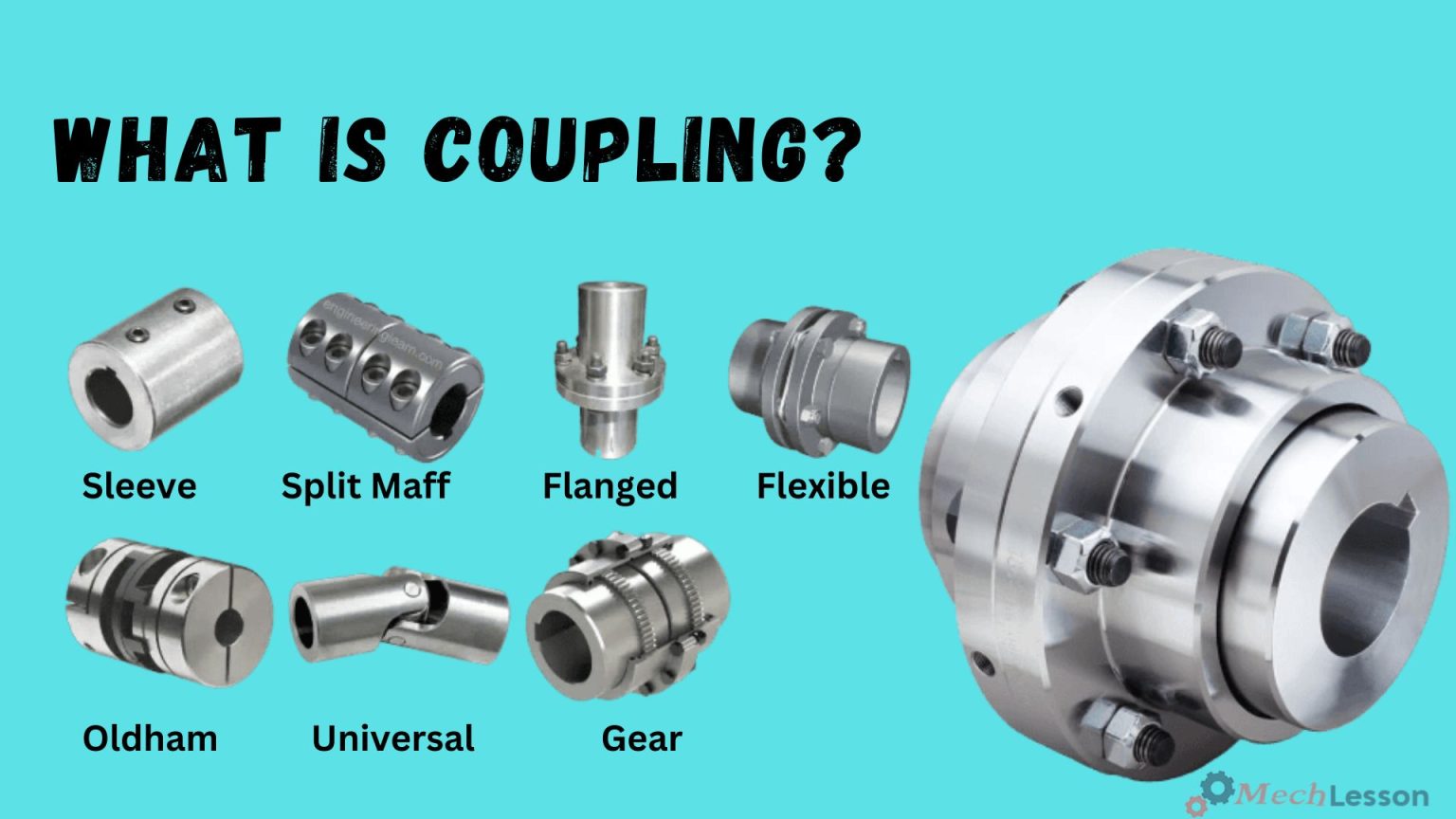
The various types of coupling are rigid, sleeve or muff, clamp or split-muff (also known as compression coupling), flange coupling, flexible, bushed pin-type, universal, and Oldham coupling. Some other types of coupling include gear, bellow, jaw, diaphragm, fluid, constant speed, and variable speed coupling.
Rigid Coupling
When two shafts align perfectly, we employ rigid couplings. They are only suitable in close alignment. Their examples include sleeve or muff coupling, split-muff coupling, and flange coupling.
Sleeve or Muff Coupling
In the construction of these types of couplings, the shaft, key, sleeve, or muff are the major components. Additionally, we use a hollow cylinder whose inner diameter matches the shaft.
We use a gib head key to secure it over the ends of the two shafts. Power transmission occurs from one shaft to the other shaft by means of a key and a sleeve. All the elements must be strong enough to transmit the torque.
Learn about Lever with this detailed guide!
Clamp, Split-Muff or Compression Coupling
These types of couplings are also known as split muff couplings. Cast iron forms the two halves of the muff or sleeve, which bolt together. A stud is also used to connect the two halves together.
Both shaft’s ends are connected to each other, and a key is fitted in the keyway located on the shafts. Bolts and nuts hold the two ends of the muff together, one attached from below and the other from above.
Flange Coupling
Flange coupling comprises two cast iron flanges fitted at the end of each shaft. Bolts complete the drive by bolting these flanges together. Bringing two tubes together in a sealed manner can represent these types of flange coupling.
In their construction, one of the flanges has a projected portion, and the other flange has a similar recess. We bring the flange ends together to ensure correct alignment without creating resistance for the material passing through them.
These types of couplings help to bring the shaft into the same line and to maintain alignment. We couple the two flanges together using bolts and nuts.
Pressurized piping systems typically employ these couplings under heavy loads. There are two types of flange couplings: unprotected and protected, as well as marine flange couplings.
Flexible Coupling
We use flexible types of couplings to connect two shafts with both lateral and angular misalignments. A few types of flexible couplings are the universal coupling, the Oldham coupling, the bellow coupling, the jaw couplings, and the diaphragm coupling.
Bushed Pin-Type Coupling
The bushed pin types of couplings are used for slightly parallel misalignment, angular misalignment, or axial misalignment of the two shafts. They bear a strong resemblance to the rigid flange coupling—in fact, the modification is quite similar.
They consist of two halves that are dissimilar in construction, known as pins and rubber bushes, which are used over pins.
Universal Coupling
These types of couplings are known as Hooke’s couplings. We use them when two shaft axes intersect at a small angle and the inclination between the two shafts remains constant. Only in actual practice can this occur, and it varies as the motion shifts from one shaft to another.
The transmission of power widely uses universal couplings. The transmission from the gearbox to the differential of the automobile contains these couplings.
In these cases, the gearbox uses two universal joints: one at the propeller shaft end and one at the differential end. Several drilling machines and milling machines also use universal coupling to transmit power to their respective spindles.
Oldham Coupling
When two shafts have a lateral misalignment, we use Oldham couplings. They consist of two flanges A and B with slots and a middle floating part E with two tongues T1 and T2.
Pins fix the middle part of the device, attaching it to flanges and floating parts. Flange A accommodates the T1 tongue, enabling back and forth motion, while flange B accommodates the T2 tongue, enabling vertical motion of the parts.
Gear Coupling
The gear couplings are the modified version of flange couplings. The large size of the teeth enables the gear coupling to transmit high torque. Instead of assembling the flange and hub as a single part, they do so separately.
In their construction, each joint has a 1:1 gear ratio internal and external gear pair. Furthermore, gear couplings are limited to angular misalignments of about 0.01–0.02 inches in parallel and 2 degrees in angular.
Heavy-duty applications that require high torque transmission similarly use gear couplings and universal joints.
You should learn about timing chain with this detailed guide!
Bellow Coupling
These types of couplings are flexible couplings with twin coupling ends known as hubs. They have excellent torsional rigidity to accurately transmit velocity, angular position, and torque. Bellows couplings are usually made up of stainless steel.
High-precision positioning necessitates their use. Bellow couplings feature thin walls and exhibit minor flexibility in terms of angular, axial, or parallel misalignment. Welding connects the hubs to the coupling below.
Jaw Coupling
Motion control applications also use jaw couplings for general-purpose power transmission. Their design transmits torque, reduces system vibrations, and adjusts misalignment to further protect other components from damage.
Jaw couplings are beneficial because they can handle angular misalignment and reactionary loads due to misalignment. Also, they have good torque-to-outside-diameter capability, and they have good chemical resistance and decent dampening capability.
Diaphragm Coupling
These types of couplings are non-lubricated couplings used in high-performance turbomachinery and transmitting torque. They also serve to correct misalignment between the shafts of equipment.
Diaphragm couplings transmit torque from the outside to the inside diameter and vice versa. They use a single or a series of plates for the flexible members and allow angular, axial, or parallel misalignment. When high torque and high speed are required, we use diaphragm couplings. Finally,
Fluid Coupling
Fluid types of coupling are also known as hydraulic coupling. They are hydrodynamic devices used to transmit rotating mechanical power through the acceleration and deceleration of hydraulic fluid.
There is an impeller on the driving shaft (input) of the device, and a runner is located on the driven shaft (output). The impeller acts as a pump, and the runner acts as a turbine.
Learn about Cam Phaser with this detailed guide!
How Does Coupling Work?
A coupling device operates in a less complex and easily understandable manner. It connects two shafts, either of the same or different diameters, together.
The motor is transmitting power from the drive side, and the propeller is on the drive side. The coupling does not transfer the heat, etc., of the motor to the driven side. We can separate flexible coupling into two groups: metallic and elastomeric.
The metallic types use freely fitted parts that roll or slide against one another, on the other hand. Additionally, non-moving parts bend to compensate for misalignments.
Elastomeric types, on the other hand, get their flexibility from elastic or plastic parts that don’t move and transfer torque between metal hubs. Watch the video below to clearly understand the workings of coupling.
A shaft coupling connects a motor’s driveshaft to its driven shaft to transfer power. The mechanism introduces mechanical flexibility to provide tolerance for shaft misalignment. Shaft coupling is the modern term for coupling.
Requirements of a Good Coupling
Here are the requirements to consider when choosing a good coupling system.
- Coupling should be able to transmit torque from the driven shaft to the driven shaft.
- It should align the shafts properly.
- Couplings should provide safety to man and machine in case of coupling failure.
- Couplings should be able to be dismantled for the purpose of maintenance.
- Finally, couplings should be adjustable.
Advantages and Disadvantages of Coupling
Advantages:
Below are the benefits of coupling in their various applications.
- Designs are less complex.
- They absorb mounting errors between the axes of the driving side (turning side)
- The process involves the transmission of power.
- It absorbs vibration from the driving side and protects surrounding products.
- Do not transfer heat from the motor on the drive side, etc., to the driven side.
- These problems can be avoided with couplings, which transfer torque and fix any parallel, angular, or axial misalignment between drive components.
- When installed correctly, couplings can also reduce vibration, minimize noise, and protect driveshaft components.
- They transfer power and torque between two rotating shafts, like those in motors, pumps, compressors, and generators.
- Couplings reduce uneven wear on the bearing, equipment vibration, and other mechanical troubles due to misalignment.
You should learn about chain drive with this detailed guide!
Disadvantages:
- Cost of initial setup
- Require a skilled engineer for proper setup
- Poor coupling selection can cause damages
- Require maintenance
- They wear out with time
Conclusion
Couplings are vital mechanical components used to connect two rotating shafts in machinery, allowing for the transmission of power and torque while accommodating misalignment, absorbing shock loads, and reducing vibration.
Choosing the right type of coupling—whether rigid, flexible, or fluid—depends on the application, alignment condition, and operational requirements. Proper installation and maintenance of couplings improve system efficiency, reduce wear on components, and extend the life of the machine.
Learn about Conveyor with this detailed guide!
Frequently Asked Questions (FAQs)
What is a coupling in mechanical systems?
A coupling is a mechanical device used to connect two shafts together for the purpose of transmitting power.
What are the main types of couplings?
- Rigid Coupling: No flexibility; used where precise shaft alignment is possible.
- Flexible Coupling: Accommodates misalignment and vibration.
- Fluid Coupling: Uses fluid dynamics for smooth torque transmission.
What is the function of a coupling?
Couplings transmit power, accommodate misalignment, reduce transmission of shock and vibration, and sometimes allow for limited axial movement.
Where are couplings commonly used?
- Pumps
- Compressors
- Motors
- Generators
- Conveyors
- Industrial machinery
What causes coupling failure?
- Misalignment
- Overload
- Improper installation
- Lack of lubrication (in some types)
- Wear and tear over time
How can I select the right coupling?
Consider:
- Torque and power requirements
- Shaft size and speed
- Type of load
- Degree of misalignment
- Environment (temperature, corrosion, etc.)
Can couplings be repaired?
Minor damage might be repairable, but usually worn or failed couplings should be replaced to avoid further machinery damage.